
Introduction
Manfred Moser converted a Commodore SX-64 to a TFT display in August 2023. The conversion was done based on the information provided on this Website.
In the course of the conversion Manfred described his procedure at Forum64.de in several posts and documented it in detail with pictures. From these posts this manual was summarized.
Notes to the manual:
1. the manual only describes the conversion of the SX-64 itself.
2. how to patch the controller board of the TFT display to activate the S-Video output is not described. Instructions for this can be found in the project files (in the meantime you can also buy pre-patched displays).
3. it is not described how to manufacture (order), assemble and solder the replacement controller board.
4. it is not described how the necessary 3D printing components are manufactured (or ordered).
5. it is not described which amplifier is used to drive the speaker.
6. this conversion deviates from the original instructions for kernal and drive switching (the instructions again point this out).
- The original usage provides that the front panel can be used to independently switch between two kernal and to switch the ID number of the SX-64 internal floppy drive between 8 and 9.
- Because in the SX-64 modified here a drive ID switch was already available via a switch, the free control line was used to switch between three Kernal instead.
7. it is also not described how to integrate a Kernal switching board into the SX-64.
All documents and files needed for the conversion can be found here:
https://allzu.net/en/tlpp/SX_64_TFT_Display_Mod.html
- Description and pictures by Manfred Moser from several posts in Forum64.de.
- Adapted, formatted, summarized and translated from German by Sven Burger.
Disclaimer:
The use of this manual, as well as the reproduction of the modification of the Commodore SX-64 described here, is solely at your own responsibility. The authors are in no way responsible for any consequential damages and direct or indirect property damage or personal injury.
by Manfred Moser
Instruction
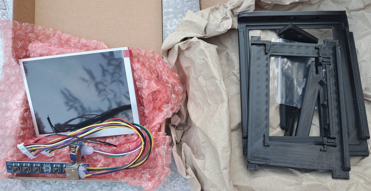
Also included were the TFT screen and a few 3D printed parts (bracket, switch extension, etc.)
To be able to adjust the picture on the new TFT display, the old CRT monitor control board (behind the flap on the right) is exchanged with a new TFT controller board to be made.
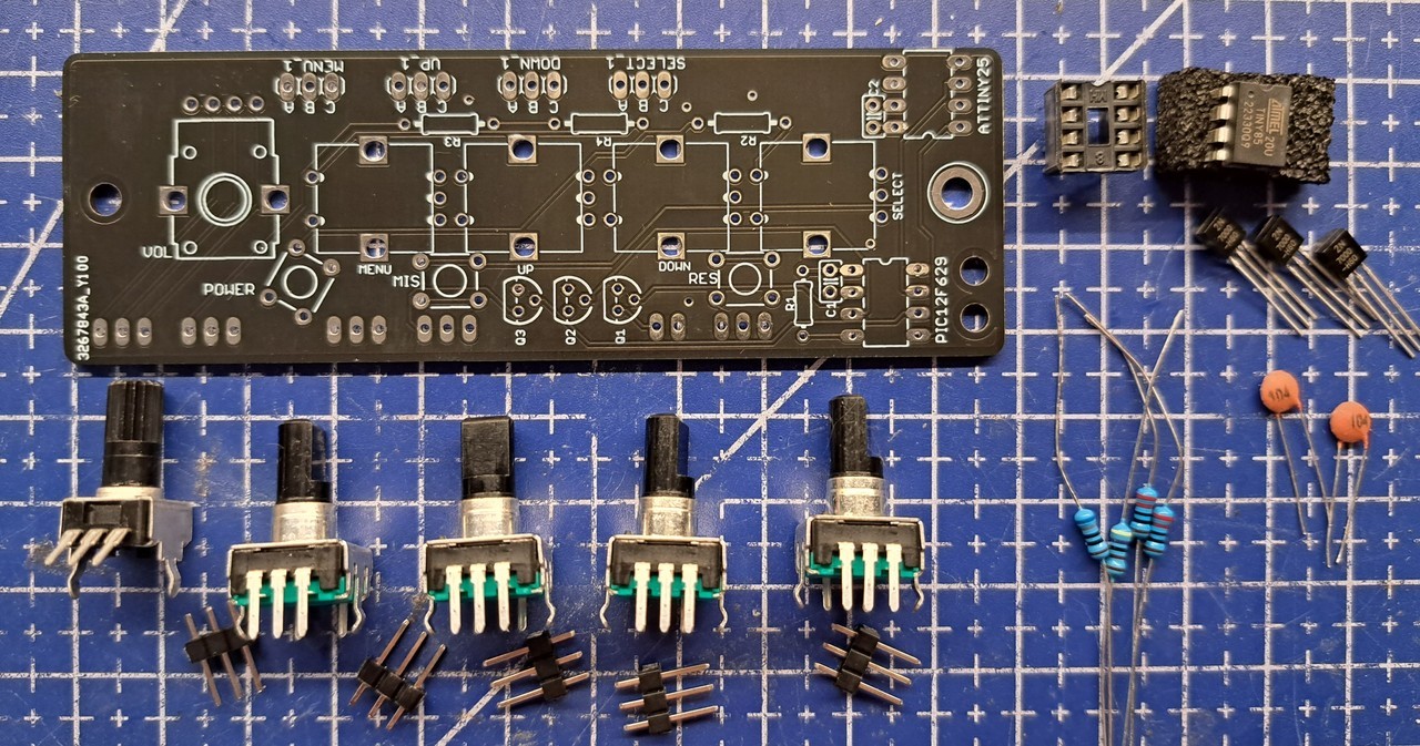
So first some orders were necessary (board at JLCPCB, potentiometer, rotary encoder, pinheader, ATTiny, MOSFETs etc.).
So first some orders were necessary (board at JLCPCB, potentiometer, rotary encoder, pinheader, ATTiny, MOSFETs etc.).
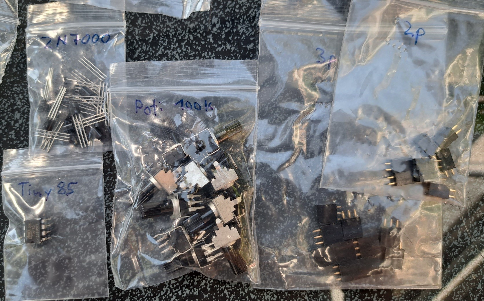
With the delivery of the circuit boards, all the necessary parts for the conversion have arrived since yesterday.
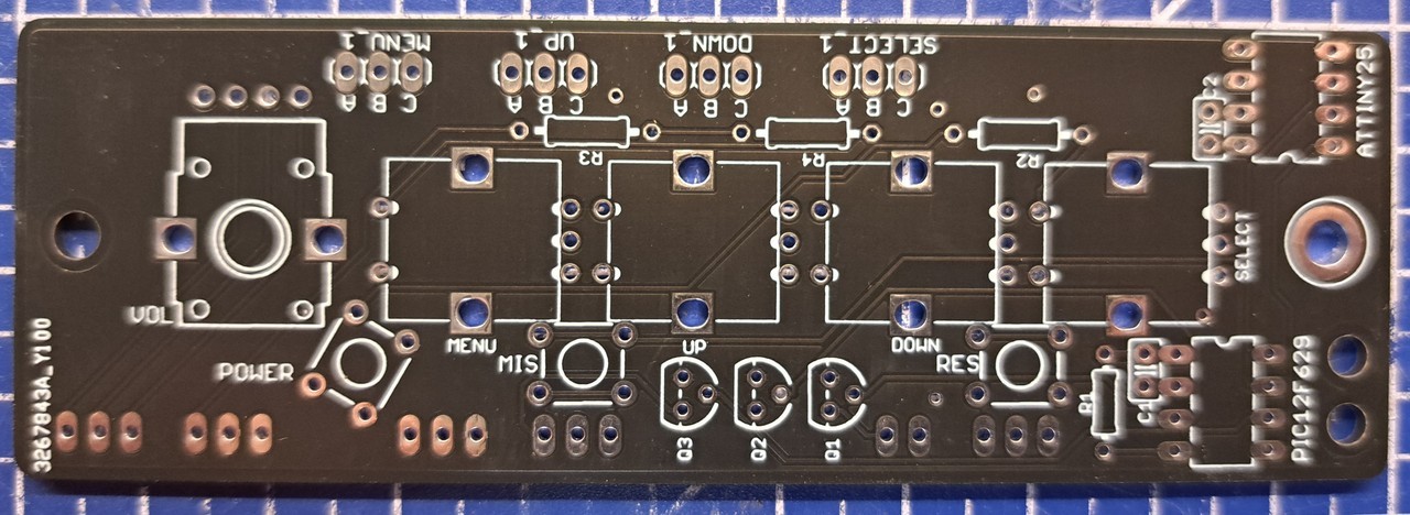
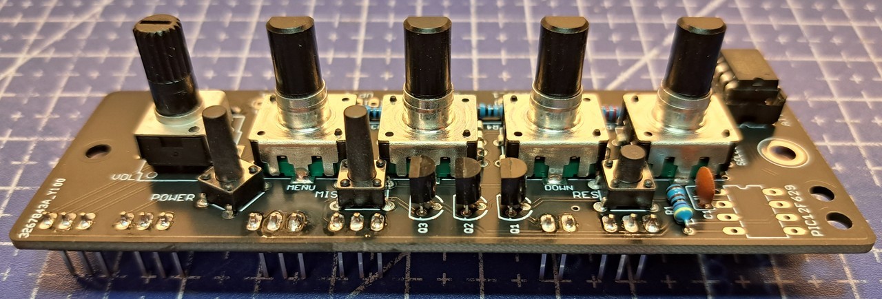
Before I even opened the SX64, the TFT controller board was built.
First I sorted the needed parts and then soldered everything. It was easy to do.
First I sorted the needed parts and then soldered everything. It was easy to do.
Before I even opened the SX64, the TFT controller board was built.
First I sorted the needed parts and then soldered everything. It was easy to do.
First I sorted the needed parts and then soldered everything. It was easy to do.
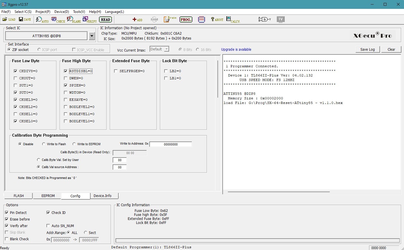
Afterwards the AT-Tiny85 was programmed with the TL866.
According to the manual only the option RSTDISBL=0 must be set for the fuses and the rest remained as preset.
According to the manual only the option RSTDISBL=0 must be set for the fuses and the rest remained as preset.
Afterwards the AT-Tiny85 was programmed with the TL866.
According to the manual only the option RSTDISBL=0 must be set for the fuses and the rest remained as preset.
According to the manual only the option RSTDISBL=0 must be set for the fuses and the rest remained as preset.
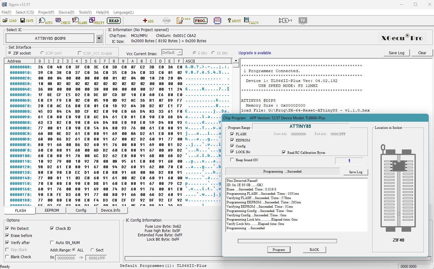
The subsequent programming was successful
The subsequent programming was successful.
Now all parts - except for the wiring - should be available, that means... stop, for the sound I still have to figure out something.
The original speaker should - for now - continue to do the job of sound output.
It will need a mounting and a small amplifier when the CRT monitor is removed. We will see... (said the blind man)
The original speaker should - for now - continue to do the job of sound output.
It will need a mounting and a small amplifier when the CRT monitor is removed. We will see... (said the blind man)
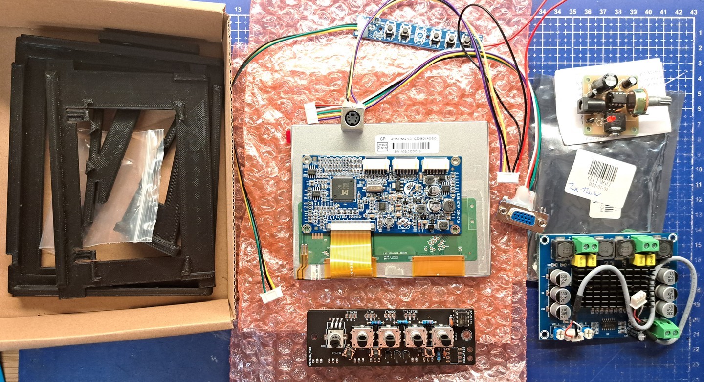
Two amplifier boards I have dug out of my collection.
Will then probably be the upper small amplifier (the lower would certainly promote the small speaker to kingdom come and also needs more than the available 12V).
Will then probably be the upper small amplifier (the lower would certainly promote the small speaker to kingdom come and also needs more than the available 12V).
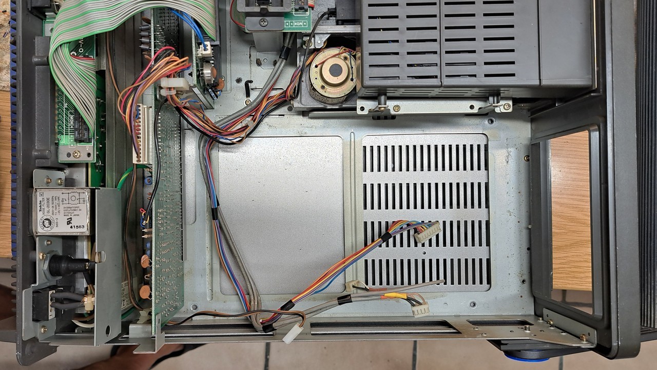
Next, the original CRT monitor was removed.
First a short test was made to see if it still works properly. He does..
First a short test was made to see if it still works properly. He does..
After that, the removal of the CRT monitor was prepared.
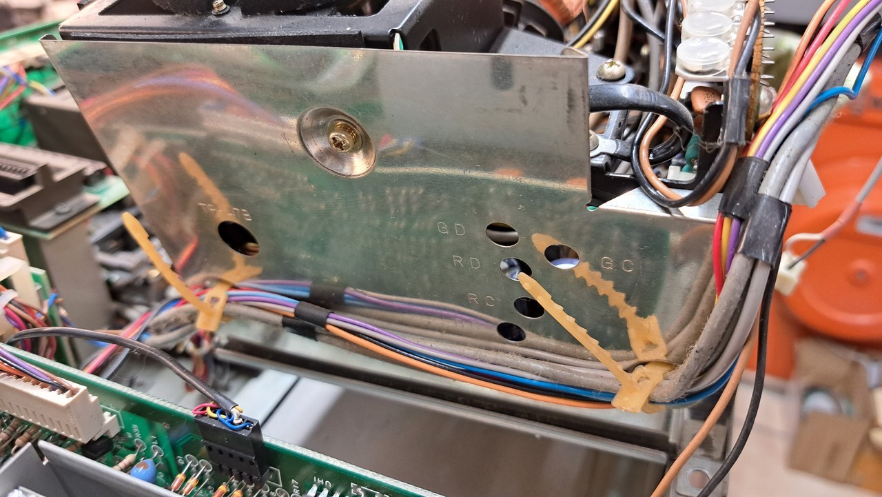
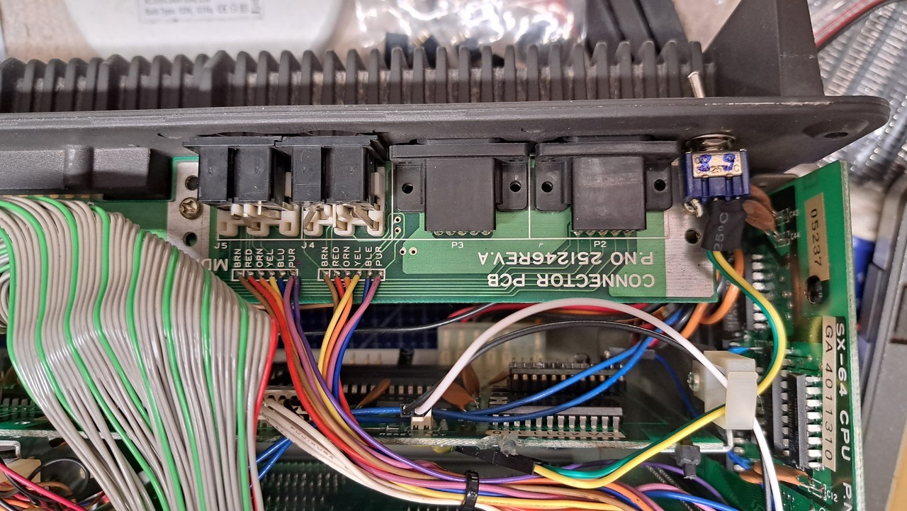
First the connectors have to be unplugged and the cable ties have to be opened
Here from the left: disconnect 12V connector, cable ties (here still closed), disconnect video connector and control connector.
First the connectors have to be unplugged and the cable ties have to be opened
Here from the left: disconnect 12V connector, cable ties (here still closed), disconnect video connector and control connector.
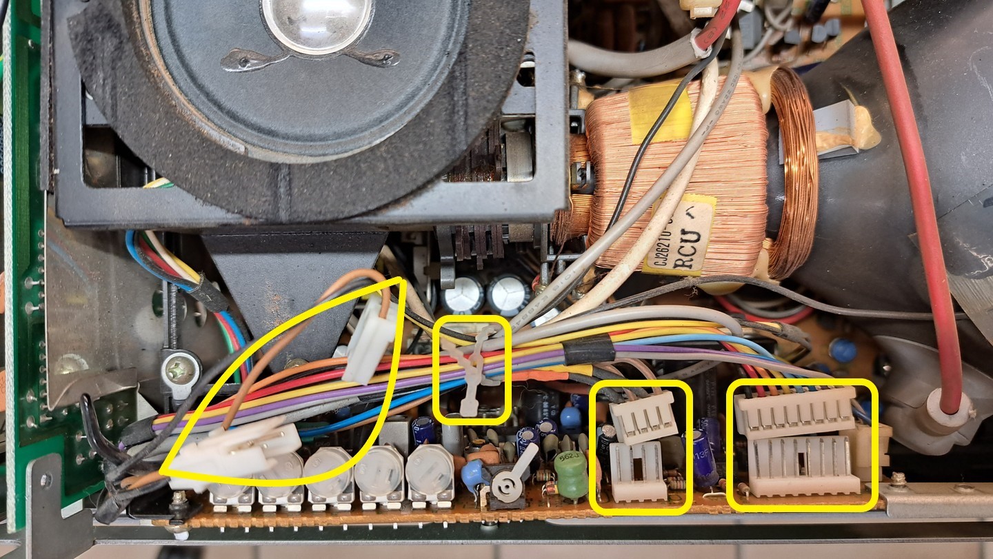
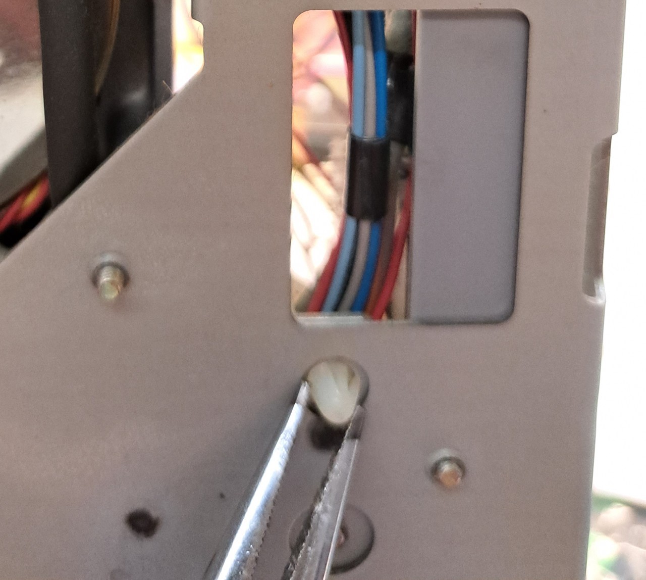
If you sort the cables, you will notice that the audio cable still goes down. I pulled this off with a needle-nose pliers. The audio cable is marked here in the picture.
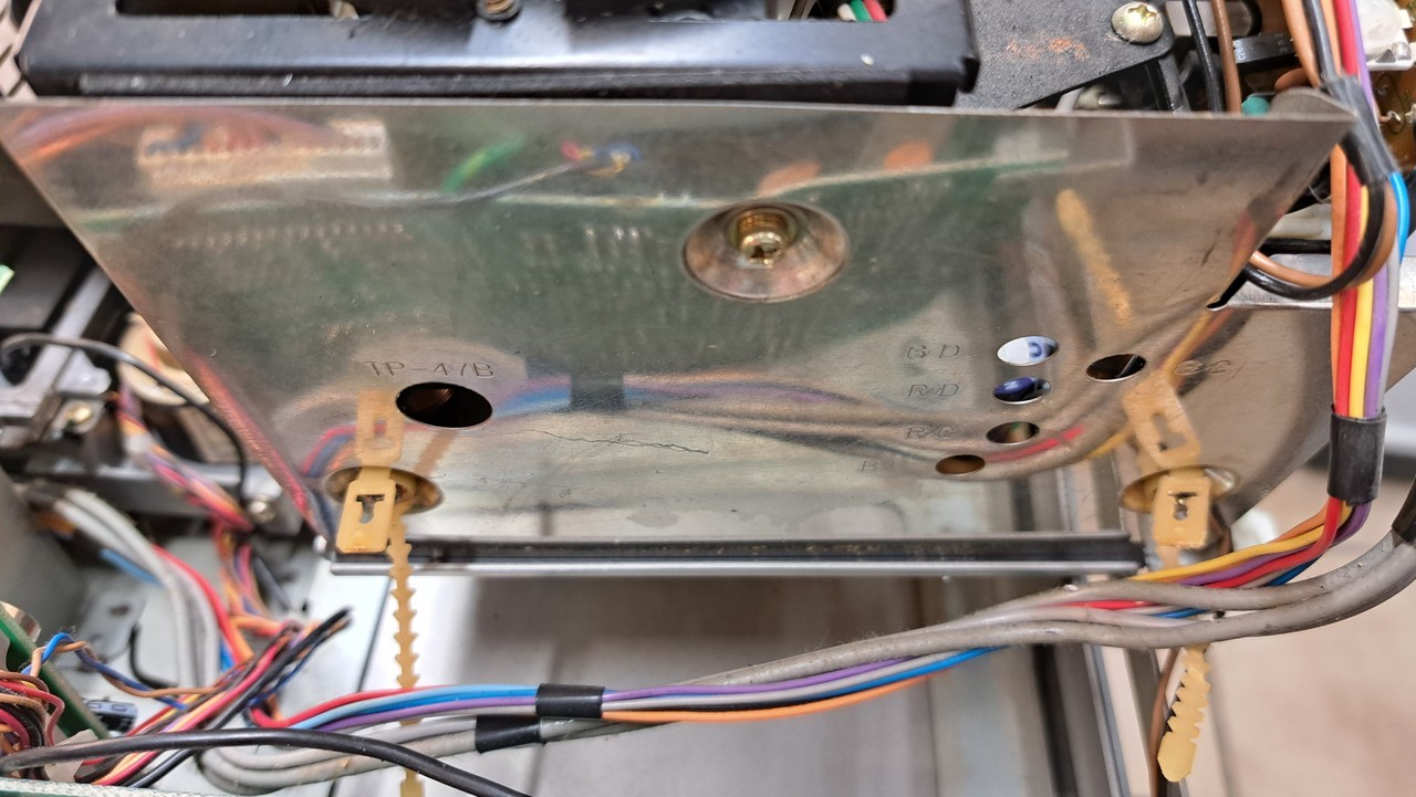
Now unscrew the four screws in the corners of the CRT monitor with a longer Phillips screwdriver. If it is magnetic, the screws will stick to it and can be easily removed.
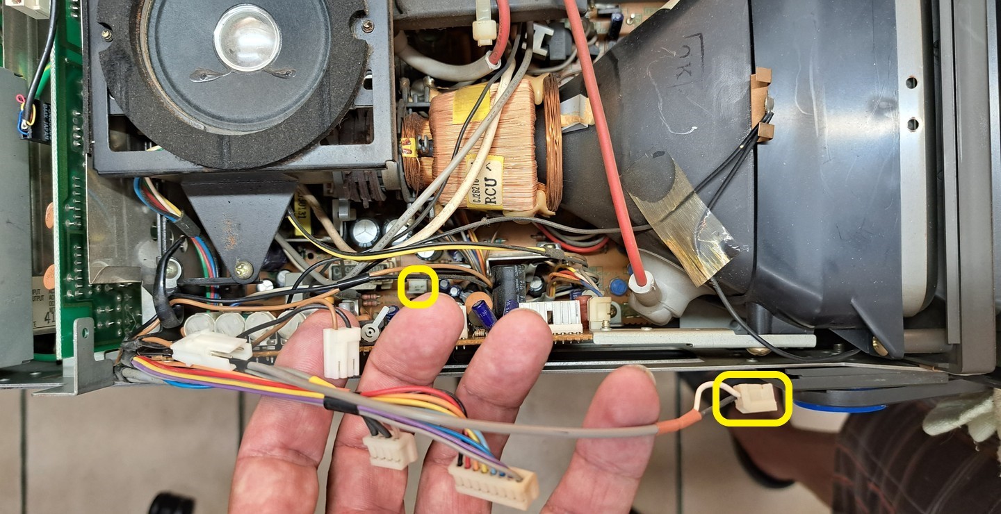
Then the monitor can be lifted. But be careful, there are still cable ties at the back.
I lifted the monitor at the front and put it down, then I could reach the cable ties at the back. Open them, then the cables can finally be put aside.
Then the monitor can be lifted. But be careful, there are still cable ties at the back.
I lifted the monitor at the front and put it down, then I could reach the cable ties at the back. Open them, then the cables can finally be put aside.
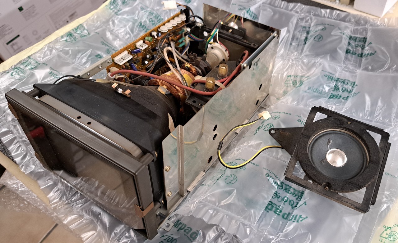
The CRT monitor is now free and can be removed.
Since I still need the speaker, it was disconnected from the monitor (remove three screws and disconnect one cable).
Since I still need the speaker, it was disconnected from the monitor (remove three screws and disconnect one cable).
I clipped the TFT display into the 3D-printed bracket and then installed it into the SX64.
You needed some longer screws. The original ones were too short and didn't grip.
Here in the picture I am already assembling the cables.
You needed some longer screws. The original ones were too short and didn't grip.
Here in the picture I am already assembling the cables.
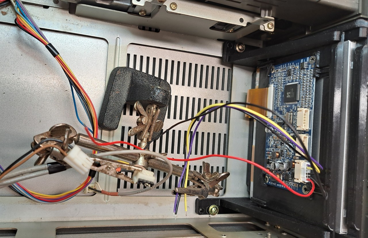
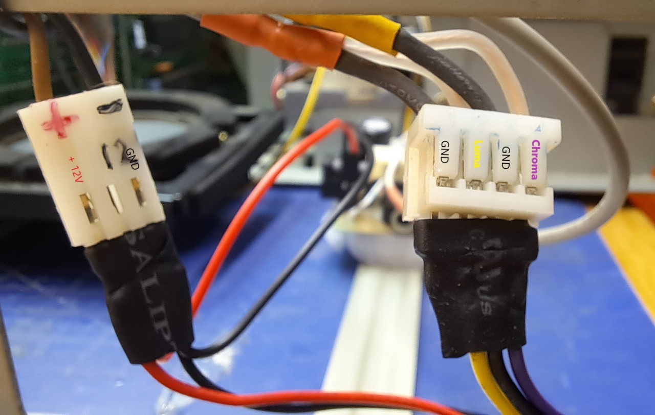
Quickly connected Luma and Chroma.
Then the 12V supply.
Measured here... black wire equals GND, brown wire equals +12V.
Then the 12V supply.
Measured here... black wire equals GND, brown wire equals +12V.
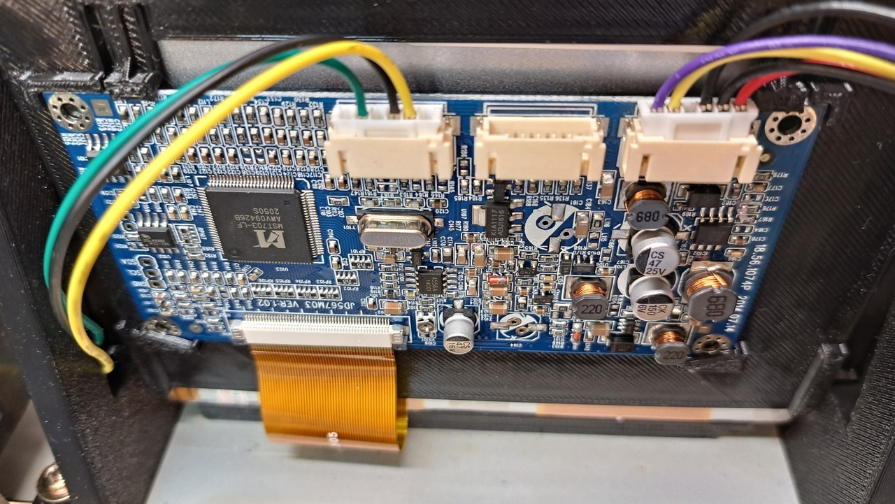
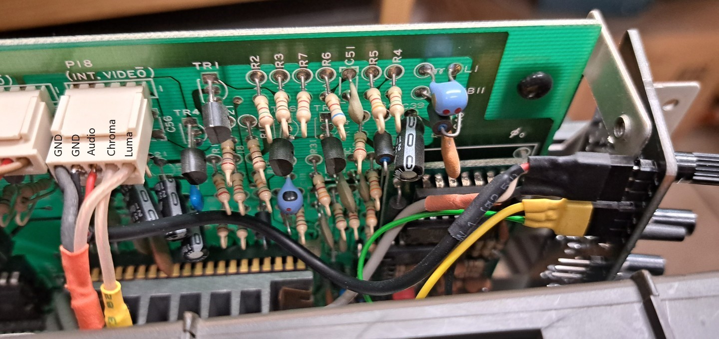
The picture shows the connections of the TFT controller board.
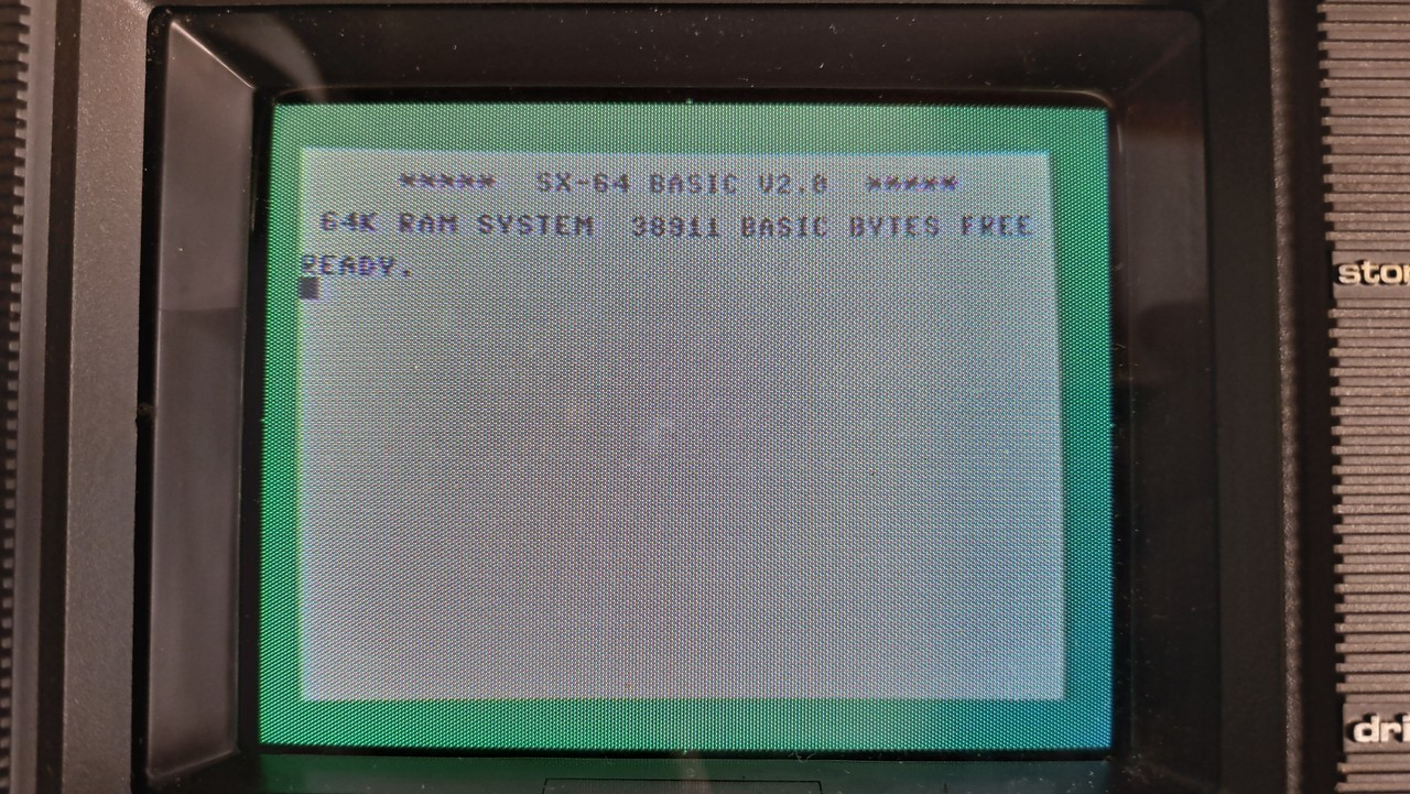
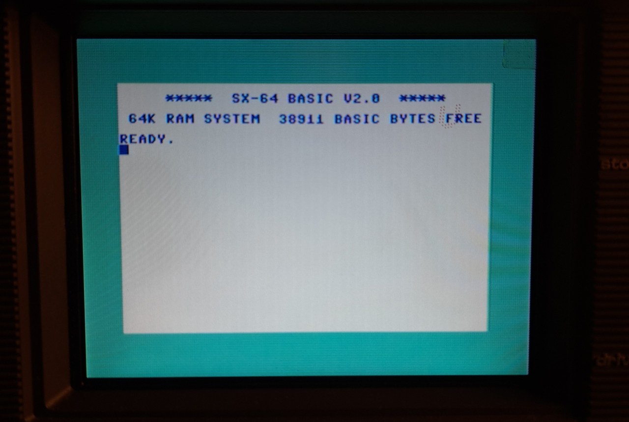
To do a first quick test run, I provisionally connected the control board that came with the new display. The previously built controller board was not used yet.
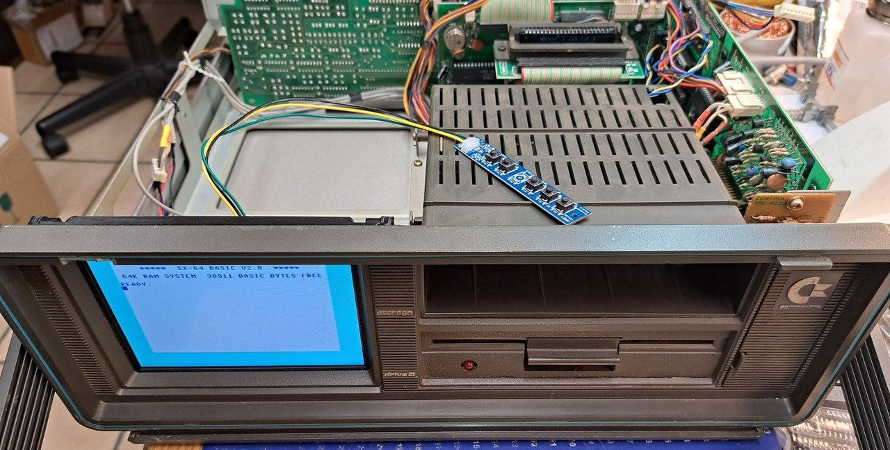
This is no comparison to the old (and skewed) image from the CRT monitor.
Looks much better in real than on the picture (my phone struggled to focus). Note also that the protective film is still stuck on the display. That's the reason for the red U in the upper right corner.
Looks much better in real than on the picture (my phone struggled to focus). Note also that the protective film is still stuck on the display. That's the reason for the red U in the upper right corner.
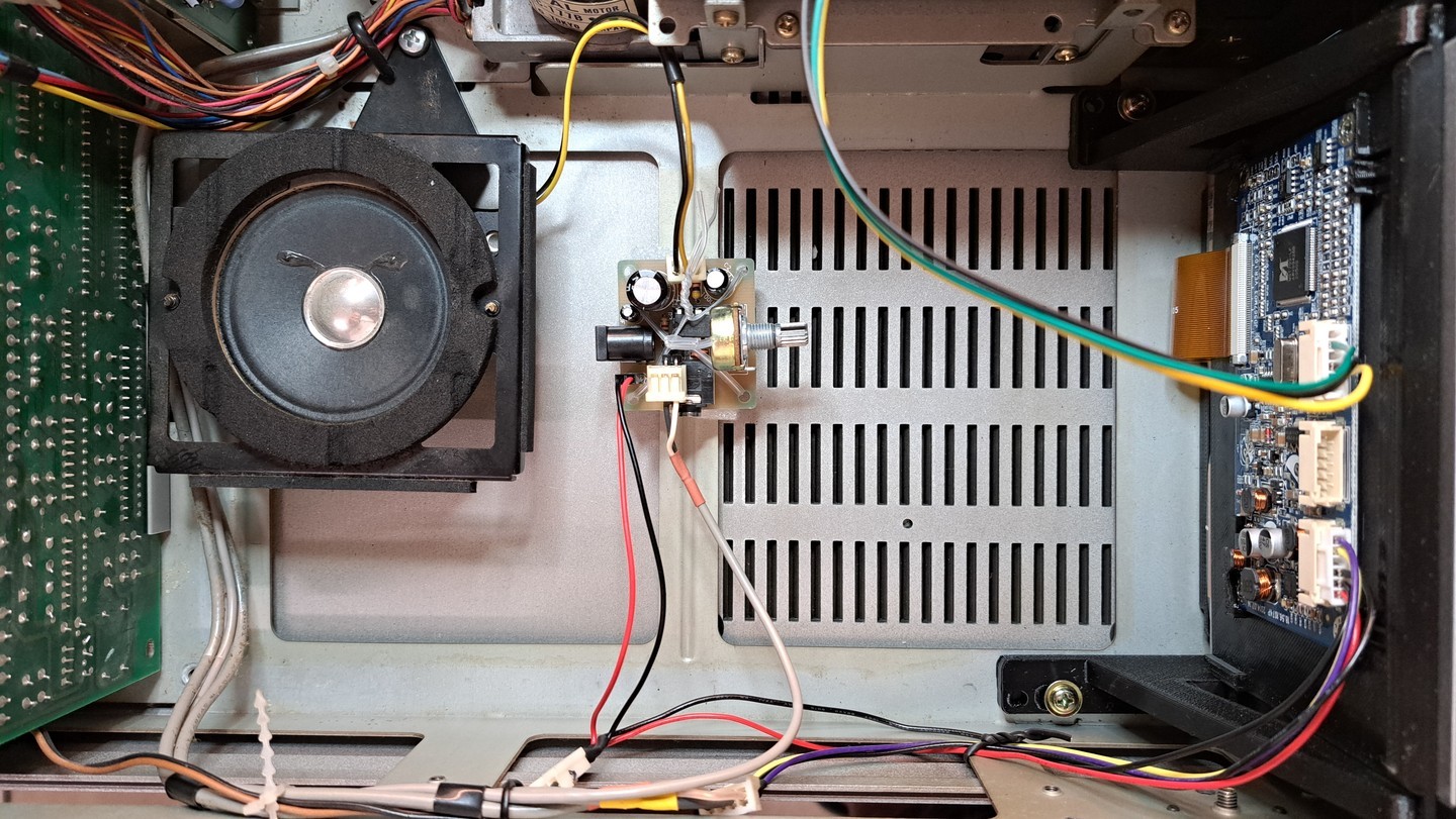
Now the sound was missing. Quickly installed the speaker. For this I used the central screw (which also holds the lower cover).
The small amplifier was placed on a foam mat and lashed crosswise with holding wire. This holds sufficiently. The speaker could be plugged on directly without modification and also the 12V supply was made by a pin header. At the audio input I had to move the GND wire in the pinheader one hole, then it was also fitting. Looks like this now:
The small amplifier was placed on a foam mat and lashed crosswise with holding wire. This holds sufficiently. The speaker could be plugged on directly without modification and also the 12V supply was made by a pin header. At the audio input I had to move the GND wire in the pinheader one hole, then it was also fitting. Looks like this now:
Now I have installed the new TFT controller board.
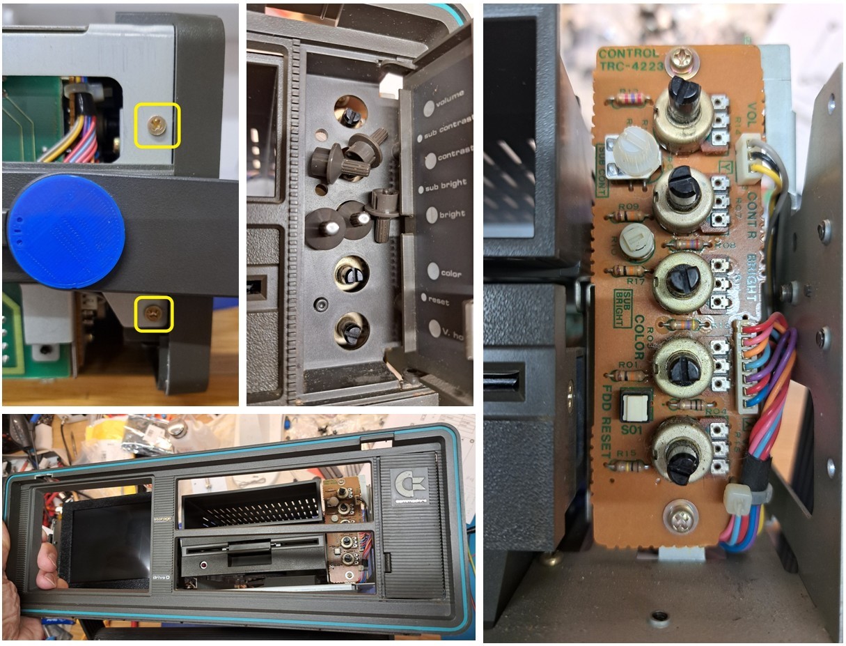
First the front cover had to be removed.
To get to the fixing screws (marked yellow at the bracket fixing) the lower case cover had to be removed as well.
On both sides 2 screws each have to be removed, then pull the knobs from the old control board to the front. Afterwards, the front cover can be removed and the (old) control board can be accessed.
Loosened the old controller board at the two fixing screws and clipped out the cable fixings from below with needle nose pliers.
The connection cable to the former CRT monitor and the cable to the FDD reset then operated out, so that the old controller board remained rebuildable.
The connection cable to the former CRT monitor and the cable to the FDD reset then operated out, so that the old controller board remained rebuildable.
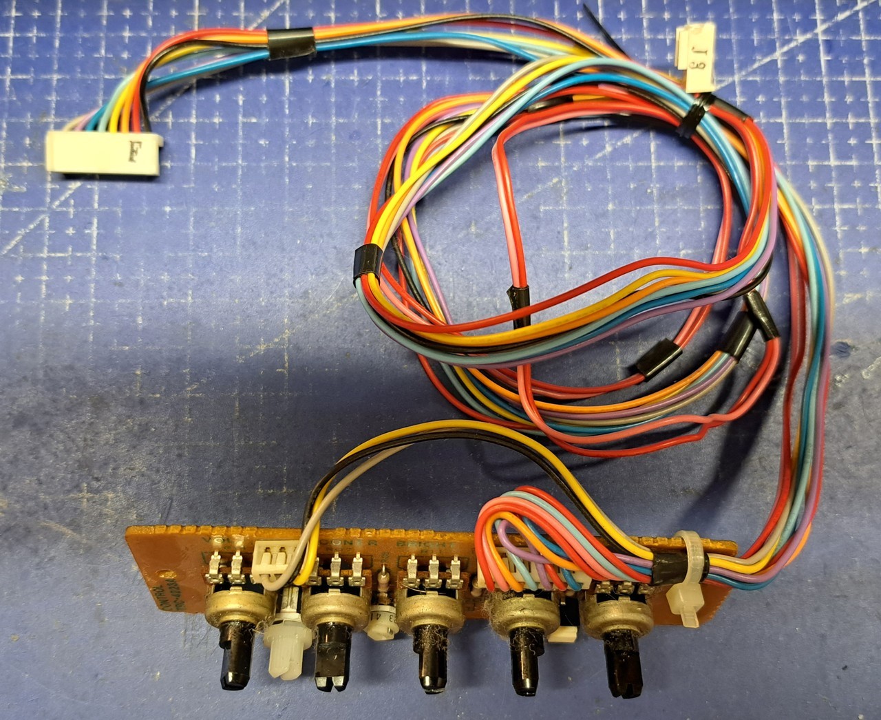
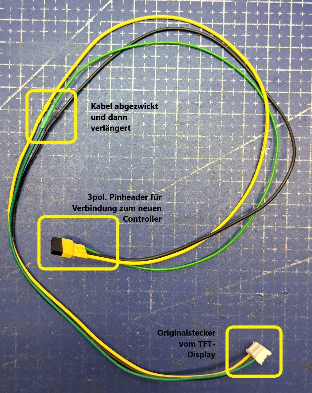
The next step was to make a connection cable from the TFT display to the new controller board.
For this I cut off the connector of the button board supplied with the TFT display, extended it and soldered a 3-pin female connector to the other end and secured it with heat shrink tubing.
For this I cut off the connector of the button board supplied with the TFT display, extended it and soldered a 3-pin female connector to the other end and secured it with heat shrink tubing.
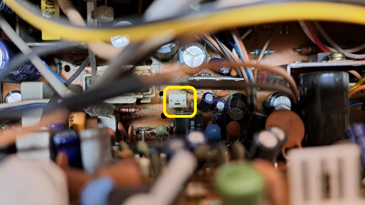
To loop in the volume potentiometer, the audio connection from the SID output to the amplifier had to be disconnected and routed via the new TFT controller board. To do this, disconnect the connector on P18. The white wire carries the audio signal, next to it the audio ground (black).
These two wires have been unclipped from the connector. To do this, press in the flap with a thin screwdriver, then you can pull the wire out of the connector.
These two wires have been unclipped from the connector. To do this, press in the flap with a thin screwdriver, then you can pull the wire out of the connector.
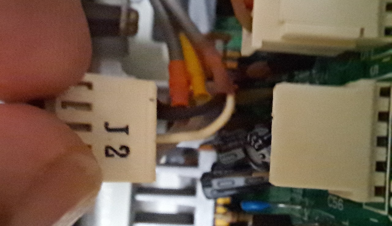
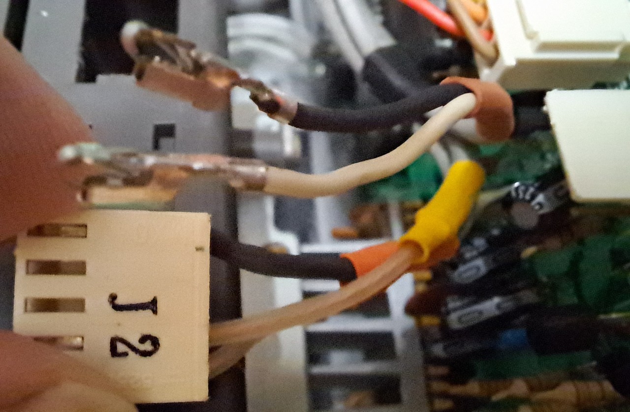
The two plug contacts were snipped off and soldered to a piece of shielded cable (black cable) and then clipped back into the white connector (J2).
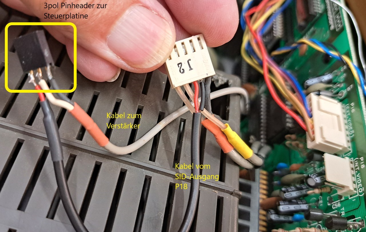
On the other side of the black cable, a 3-pin female connector was soldered (to pin 1). This will be connected to the new TFT controller board later.
The light cable going to the amplifier was attached to pin 2 (audio) and pin 3 (GND)
On the other side of the black cable, a 3-pin female connector was soldered (to pin 1). This will be connected to the new TFT controller board later.
The light cable going to the amplifier was attached to pin 2 (audio) and pin 3 (GND)
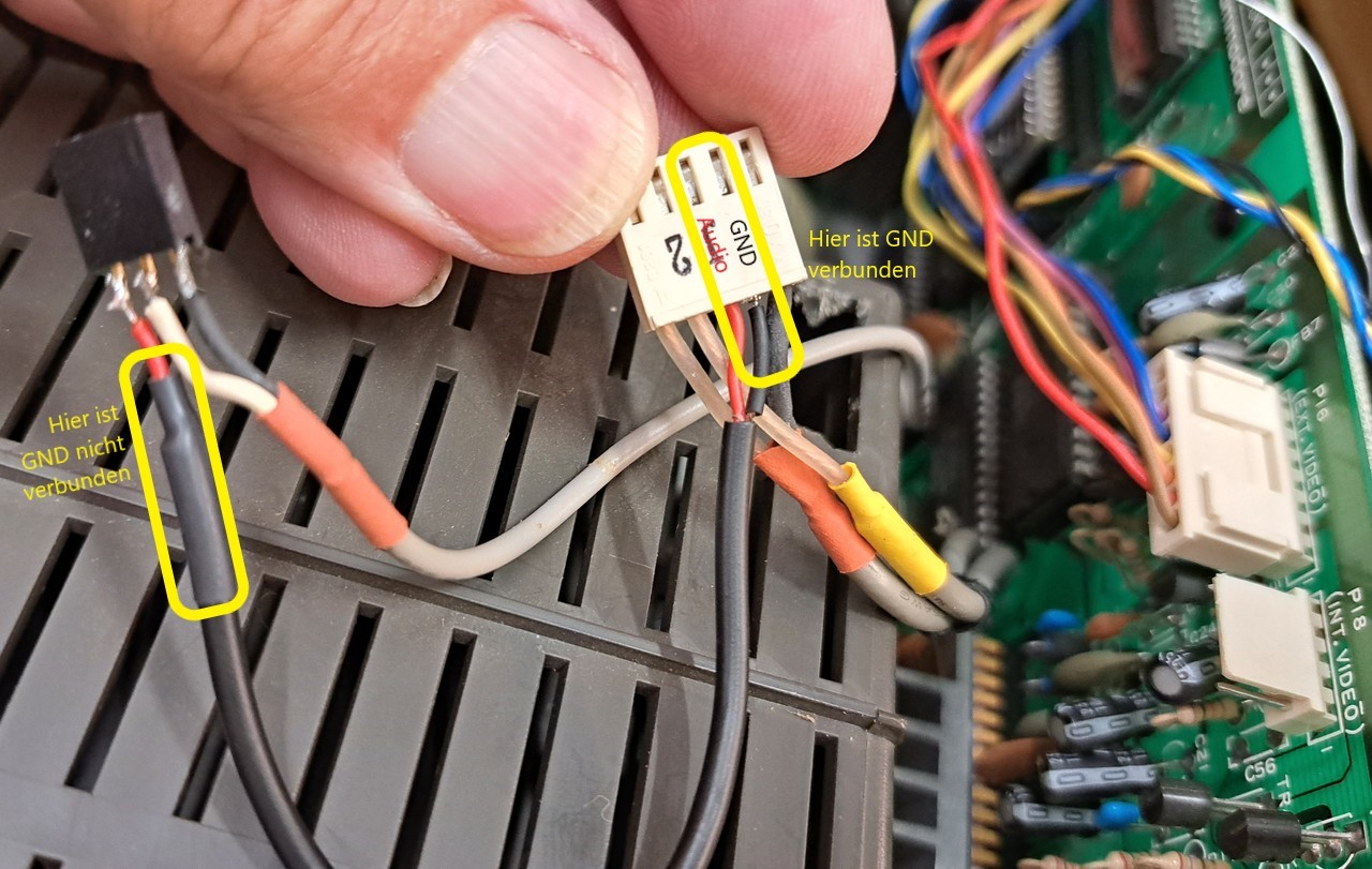
To prevent hum, only shielded cable should be used for the audio connection. You have to be careful not to build in a ground loop.
Therefore it is important to connect only one side of the shielding to GND!
That's why the shielded (black) cable from the SID output to the potentiometer is only connected to GND on one side (the one from which the signal derives).
Therefore it is important to connect only one side of the shielding to GND!
That's why the shielded (black) cable from the SID output to the potentiometer is only connected to GND on one side (the one from which the signal derives).
Here the audio connection already connected to the new TFT controller board.
Thus, I first screwed on the new TFT controller board to test whether the display and the volume can be controlled.
The special functions (reset, drive switching, kernal switching) are still missing. That will come later.
The special functions (reset, drive switching, kernal switching) are still missing. That will come later.
The control works perfectly up to this point. Here's a short video:
The final spurt. The special functions 3-way Kernal Switch, Complete Reset and Floppy Reset are now working.
But one after the other:
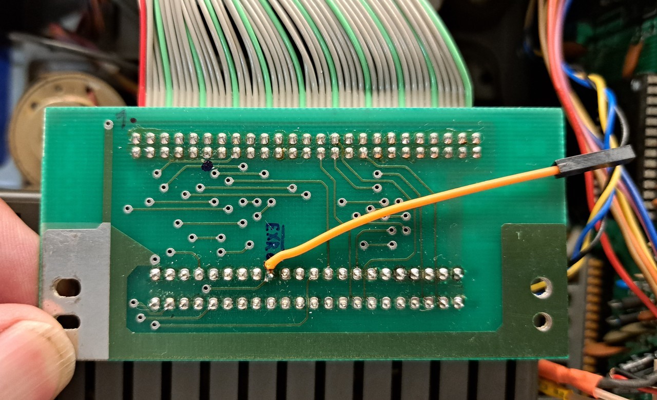
For the EXROM reset, a cable from pin 9 on the expansion port to the controller board is needed.
It was solved with an orange dupont cable.
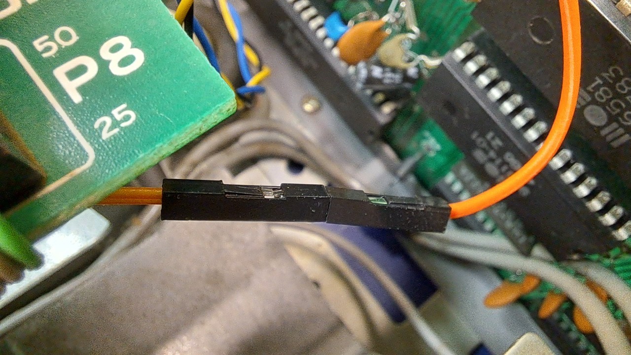
In case one would have to remove the expansion port, I have added an intermediate connector.
But one after the other:
For the EXROM reset, a cable from pin 9 on the expansion port to the controller board is needed.
It was solved with an orange dupont cable.
In case one would have to remove the expansion port, I have added an intermediate connector.
The purple wire is the normal SX reset which was tapped at serial port pin6.
The Kernal switching described on the following steps has been made somewhat different from the originally intended wiring.
In the original version it is possible to switch between two Kernals
(e.g. CBM - JiffyDOS). Furthermore the drive ID can be switched between 8 and 9 (ATTiny variant).
While in the following description a 3-fold Kernal switching without drive ID switching (because externally already existing) is described.
So please understand this part of the manual more as a general help than an exact template for the conversion.
Note S. Burger
Next up was the core switching.
This SX64 is equipped with a 3-fold core switching via two KERNALquattros. One for the SX core and one in the floppy controller.
So far this was realized by a switch with three positions. Because no hole should be drilled, the switch lay loosely in the drive tray.
It was possible to switch between Jiffydos-CBM-EXOS
The drive address switching #8/#9 is also realized by a switch on this SX64.
It is installed in an already existing hole in the rear panel and can stay there, because the hole is already there anyway.
Therefore, I converted the drive switching provided by the ATTiny to access the third Kernal.
Here is the wiring:
If the yellow wire on the KERNALquattro is connected to GND, Jiffydos is selected.
The blue wire on GND selects EXOS.
If none of the two wires is pulled to GND, then the original CBM-SX64-Kernal is active.
Here is the wiring:
If the yellow wire on the KERNALquattro is connected to GND, Jiffydos is selected.
The blue wire on GND selects EXOS.
If none of the two wires is pulled to GND, then the original CBM-SX64-Kernal is active.
The yellow and blue wires (and the black for GND) were disconnected from the switch and pin headers were crimped on instead.
These were then connected to the outputs D and K on the control board.
These were then connected to the outputs D and K on the control board.
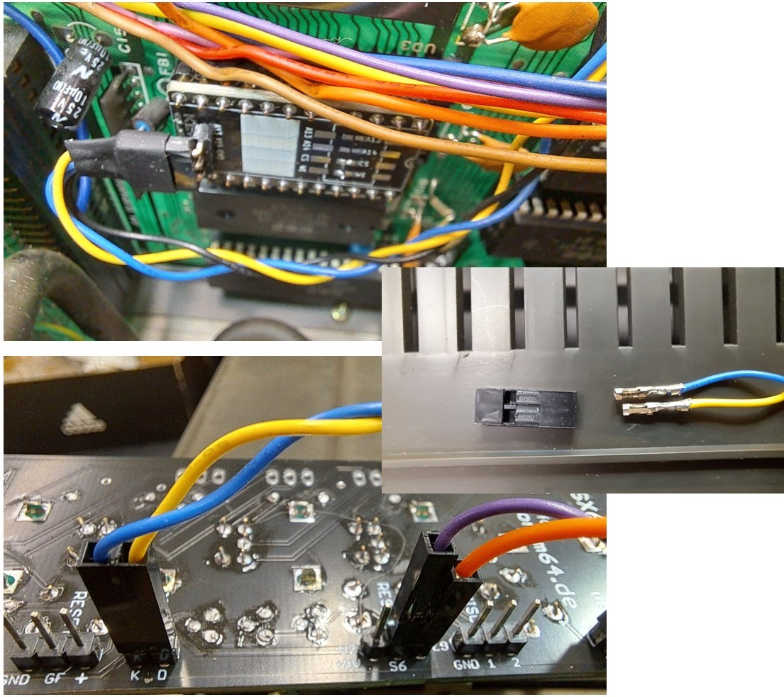
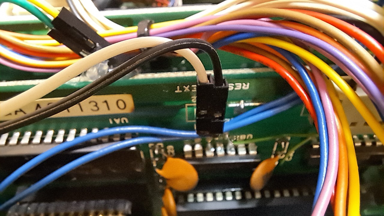
The last function to be implemented is the floppy reset (only the floppy without SX), as it is integrated in the original SX64.
You don't really need it if you can reset the SX completely, but because the lower button would have been without function otherwise, I just connected it.
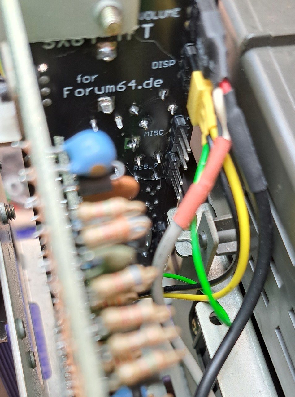
It was realized by a white and black dupont wire, one end of which is connected to the floppy controller of the SX, the other end to the TFT controller board.
You don't really need it if you can reset the SX completely, but because the lower button would have been without function otherwise, I just connected it.
It was realized by a white and black dupont wire, one end of which is connected to the floppy controller of the SX, the other end to the TFT controller board.
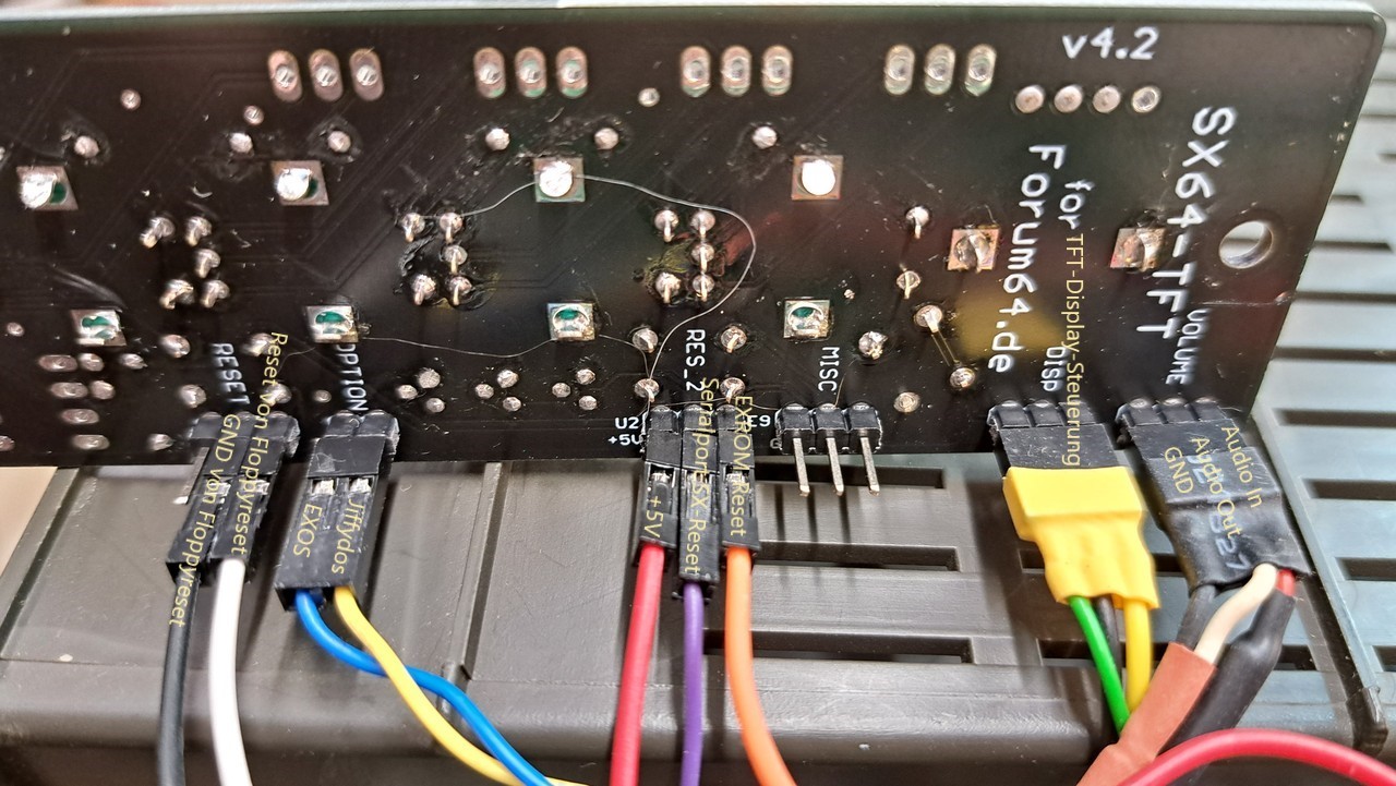
The red cable goes to pin 2 of the userport. This is the 5V power supply for the controller board.
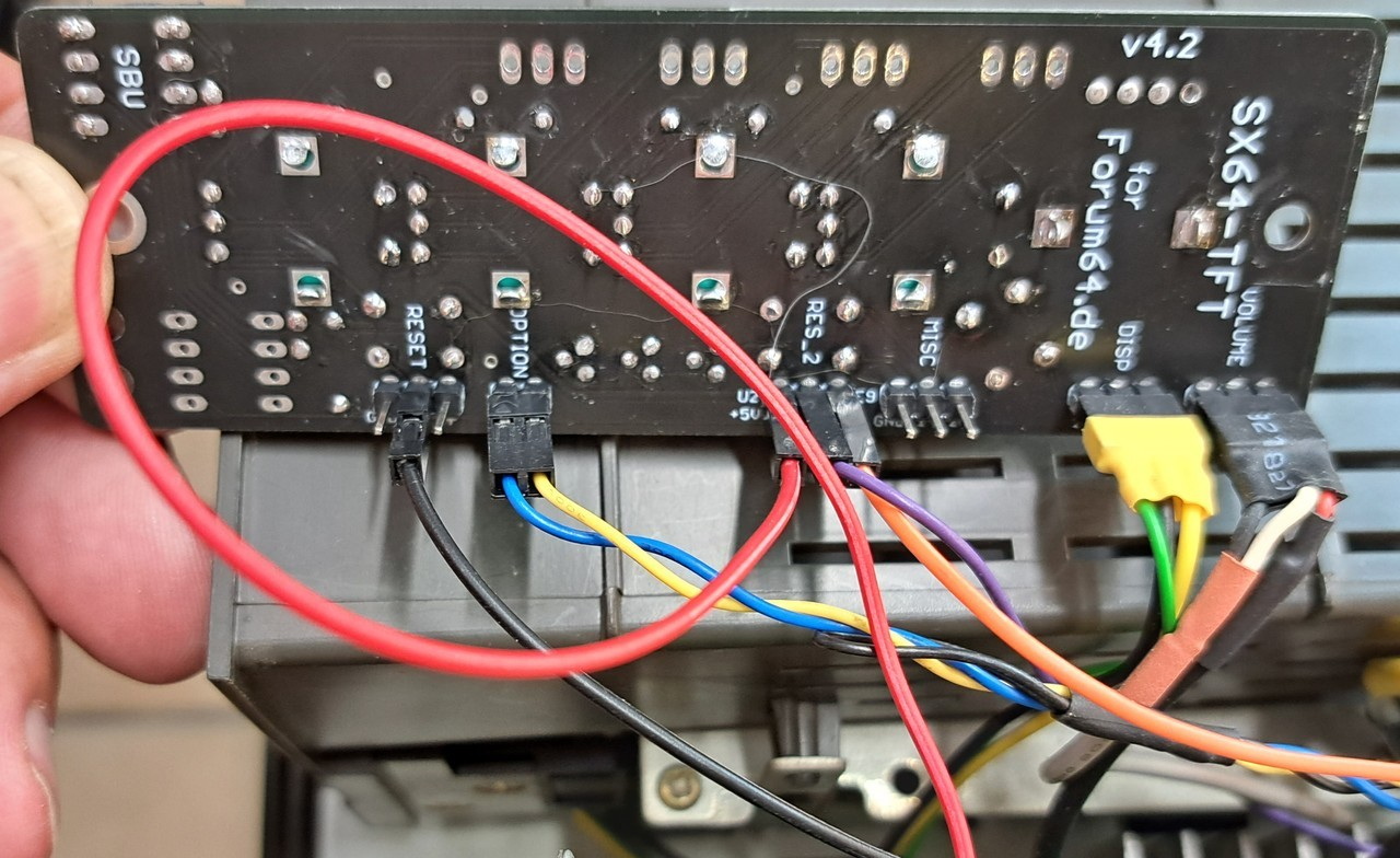
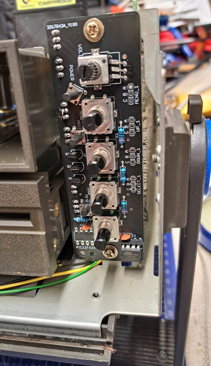
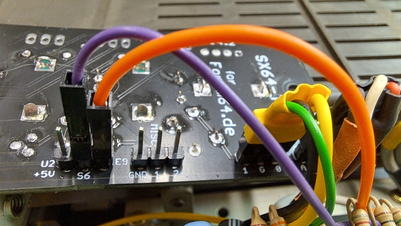
This completes the wiring. In the picture all connections are labeled again.
Note that in the picture the jumper between the GND pin and pin 1 on the MISC pin header is not yet attached. This must also be done in this step.
Note that in the picture the jumper between the GND pin and pin 1 on the MISC pin header is not yet attached. This must also be done in this step.
The controller board could finally be screwed on and tested.
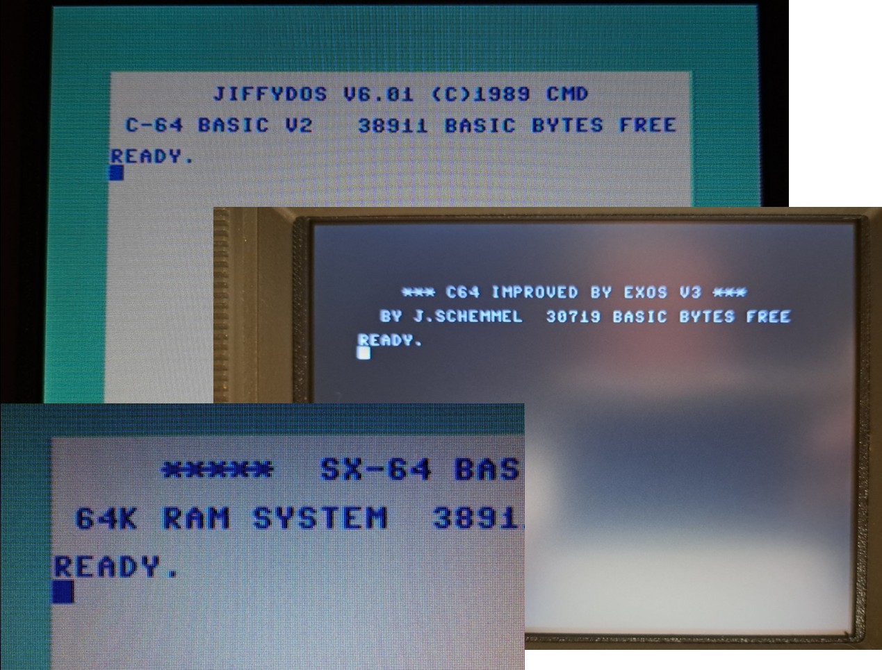
This is how it works now via the option key:
1. Press briefly - switch between CBM kernal and Jiffydos.
2. Press and hold - EXOS is now selected as the alternative kernal instead of Jiffydos.
3. Press briefly - now switch between CBM-Kernal and EXOS.
4. Press and hold again - Jiffydos is selected as the alternative kernel instead of EXOS.
5. press shortly - switch over as described under 1. (CBM - Jiffydos)
Or expressed differently:
Press briefly to switch between CBM kernal and an alternative kernal.
Which of the two alternative kernals this is (JD or EXOS) can be selected by long pressing the option key.
The last selected kernal is stored in the ATTiny and is automatically selected when the ATTiny is switched on again.
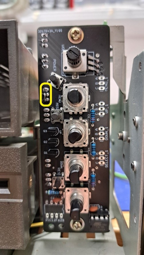
Yellow outlined you can see the bridge between pin 1 and GND on MISC connector.
Here is a video of the Kernal switching:
Now the front cover was mounted again and the control buttons from the controller board were plugged in.
Before that, the 3D-printed extensions for the two upper buttons had to be plugged on.
Before that, the 3D-printed extensions for the two upper buttons had to be plugged on.
At the first try almost everything fit. The buttons could be operated and the knobs fit perfectly on the encoders (which are only used as buttons).
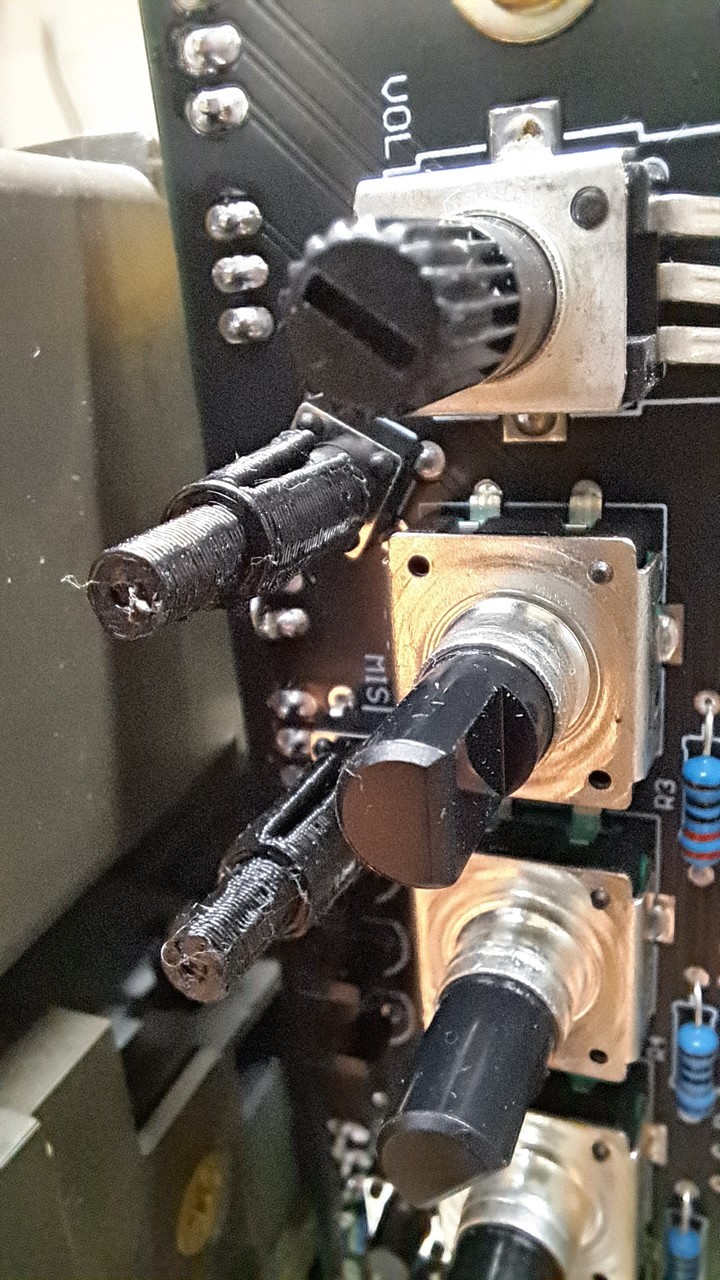
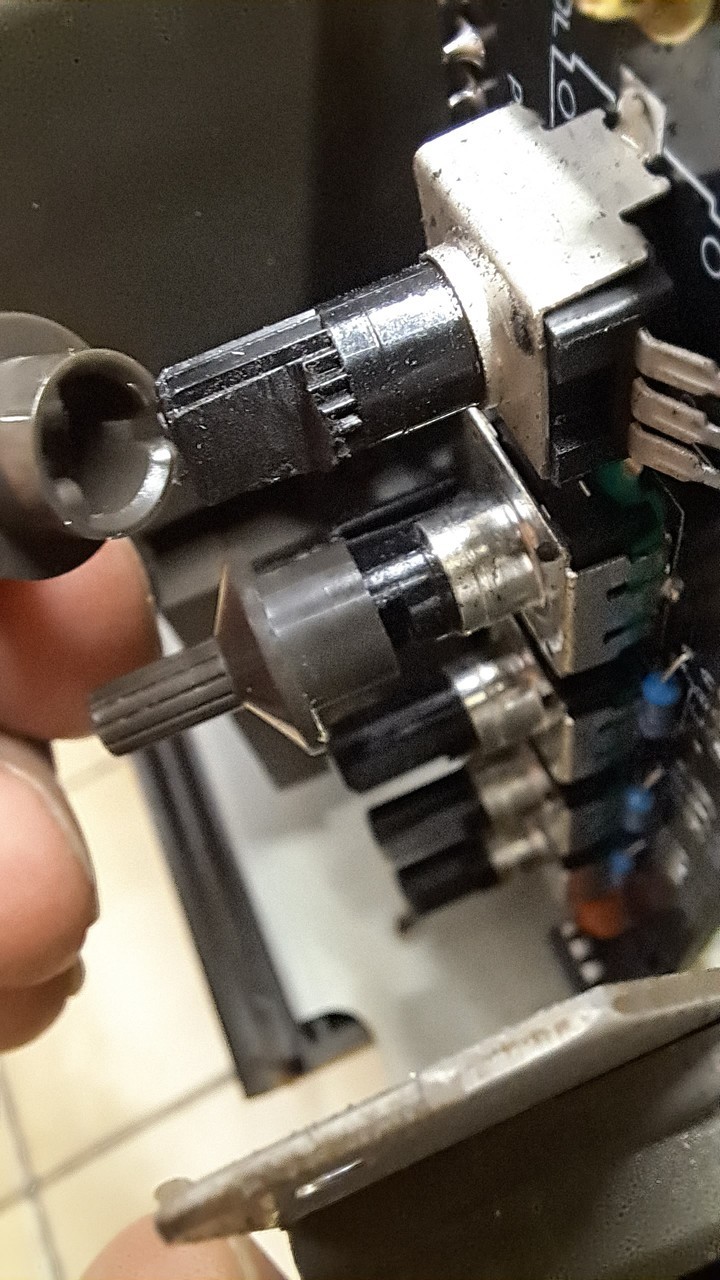
Unfortunately, I had overlooked that the potentiometer did not have a flattened axis. I had not ordered the right part from the Far East.
But what does not fit, is made to fit
Because I didn't want to mess with the original SX knobs, the front cover had to be removed again and then the potentiometer axis was flattened with a Dremel.
(This does not happen if you order the parts via the links in the parts list).
Note S. Burger
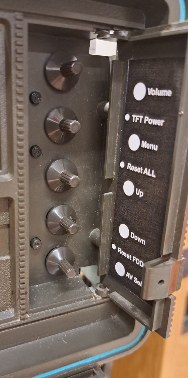
After that, the button fit perfectly on it and the front cover was mounted again. The buttons all put on and then glued on a new label for the controls.
Looks like this now, I think you can leave it like this
Looks like this now, I think you can leave it like this
Before closing the SX, I loosened the TFT display again to remove the protective film.
The picture looks even a bit better without the film. Unfortunately, the cell phone camera can't show it as nicely as it looks in real life.
The picture looks even a bit better without the film. Unfortunately, the cell phone camera can't show it as nicely as it looks in real life.
Now finally the SX was closed again and a small game was loaded via floppy disk.
Here again the description of the functions of the controller boards in the AtTiny version.
S. Burger
S. Burger
SX-64 Reset and Kernal switching with the ATtiny85
Advanced reset function. Kernal and drive ID switching for the Commodore SX-64.
For the SX-64 - TFT Monitor Controller board v4.1 / v4.2.
Microcontroller: ATtiny85
Designations:
[ ] = designation of the controlled pins on the controller board.
Extended reset function via floppy reset button:
- short key press = normal drive reset [+] [GF].
- After 1 second = reset of SX64 via [S6] Serial bus and [E9] EXrom reset on expansion port.
Options via the Misc key:
- Short key press = toggle [D] drive ID between 8 and 9 followed by reset.
- After 1 second = Toggle the [K] Kernal between Original and e.g. JiffyDos followed by a reset.
- Saving the last set options beyond the next reboot or reset.
Other:
- Hold Misc and Reset key for 1 sec until reset = reset to original settings:
Kernal = CBM, Drive ID = 8.
- For the [E9] (Hard) EXrom Reset different delay times are programmed depending on the Kernal (20ms/10ms) to cope with a possibly shortened reset routine.
- EXrom Reset timings are not tested yet (maybe not the complete memory is released).
(Works with JiffyDos - 13/07/2016).
To enable the Misc button:
1. bridge (jumpers) at the [MISC] pin header [1] with [GND].
2. on the ATtiny85, set the config fuse RSTDISBL=0.
File: SX-64-Reset-ATtiny85 - v1.1.0.hex
Last Update: 18.09.2023
The other day a forum colleague asked me if I could convert his SX-64 to a TFT display. It is the SX64, which was already repaired by me.
See also under "repaired today" and the "following" posts (in German).
The conversion should be done according to this manual from Zipcom.
The project files are stored on his web page and contain the necessary info for ordering, building and programming.
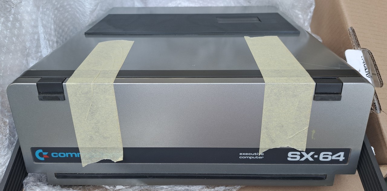
So the SX64 was shipped to me again and arrived safe and sound.
See also under "repaired today" and the "following" posts (in German).
The conversion should be done according to this manual from Zipcom.
The project files are stored on his web page and contain the necessary info for ordering, building and programming.
So the SX64 was shipped to me again and arrived safe and sound.
